There is an upper limit to the amount of electricity that can flow on an interconnection line. This limit is called total transfer capability (TTC). This article explains the four limiting factors that determine TTC and which factor sets the limit on each interconnection line in FY2026 (April 2026–March 2027). What an interconnection line is, and how Japan’s ten regional service areas and interconnection lines are configured, is explained in “Cross-Regional Interconnection Lines in Japan” in this series.
Definition of TTC
TTC is the upper limit of the amount of electricity (power flow) that can flow stably on an interconnection line. The Organization for Cross-regional Coordination of Transmission Operators, JAPAN (OCCTO), the body that calculates and publishes the TTC of interconnection lines nationwide, publishes the study conditions and calculation results at its Working Group on Cross-regional Transfer Capability.
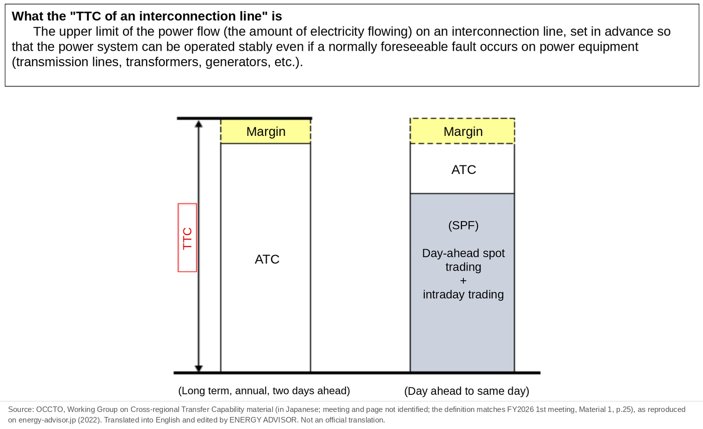
As equipment, an interconnection line is a transmission line or a converter facility. Whenever electricity flows, heat is always produced. If too much flows, the heat can damage transmission lines or break converter facilities. The whole system can also become unstable when a fault occurs. To prevent this, the limit on how much can flow is studied in advance, and the resulting upper limit is TTC.
Four Limiting Factors
On interconnection lines, as on any part of a power system, the power flow that can be carried is determined mainly by the following four limiting factors. The flow value that satisfies all four, that is, the smallest of the four limit values, becomes TTC. The limiting factor that set the smallest value is called the “binding constraint.”
| No. | Limiting factor | What it limits |
|---|---|---|
| (1) | Thermal limit (and other equipment ratings) | The upper limit of current that transmission lines and equipment can carry continuously (for converter facilities, the design rating) |
| (2) | Transient stability (synchronous stability) | The limit up to which generators can keep rotating in step even after a fault |
| (3) | Voltage stability | The limit up to which system voltage can be maintained even after a fault |
| (4) | Frequency stability limit | The limit up to which frequency can be maintained when an interconnection line trips and the areas separate |
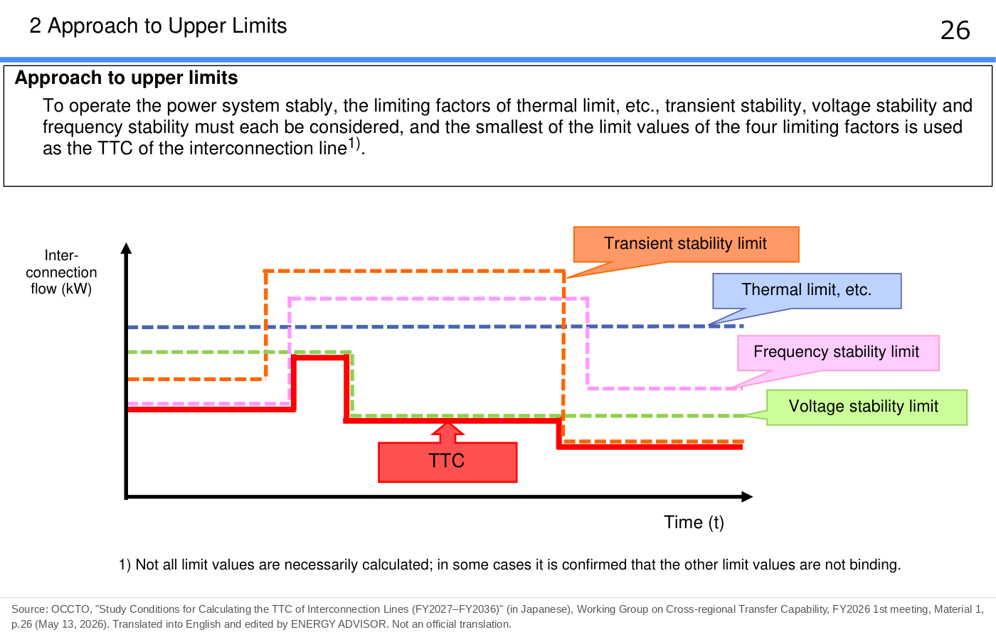
In OCCTO’s published materials, the binding constraint is shown next to each TTC value with a number from (1) to (4).
(1) Thermal Limit
When a current I (A) flows through a transmission line for a time t (s), the line heats up according to Joule’s law (Q = I²Rt), because it has a resistance R (Ω). A maximum allowable temperature is set according to the type and diameter of the transmission line and the number of conductors. The thermal capacity is the current, or the power flow (power, MW), at which that maximum temperature is reached.
The current at which the maximum temperature is reached also changes with the ambient temperature. The higher the temperature, the smaller the current that can flow. For example, the rated thermal capacity of the Mie–Higashiomi Line and the Echizen–Reinan Line in the Central-Area AC Loop is, per circuit, 2,780 MW (ambient temperature 40°C) or 2,950 MW (35°C) in summer and 3,260 MW (25°C) in winter, and the ambient temperature is set for each month to choose among them.
Frequency converter stations and AC/DC converter stations have design ratings, and these become the upper limits as they are. The thermal capacity of transmission lines and the design ratings of equipment are together called the “thermal limit (and other equipment ratings).”
The thermal limit study considers N-1 contingencies of power equipment. An N-1 contingency is a fault in which just one piece of equipment becomes unavailable. When one piece stops, its flow shifts to the other healthy equipment. The limit is set so that there is still no problem when this happens.
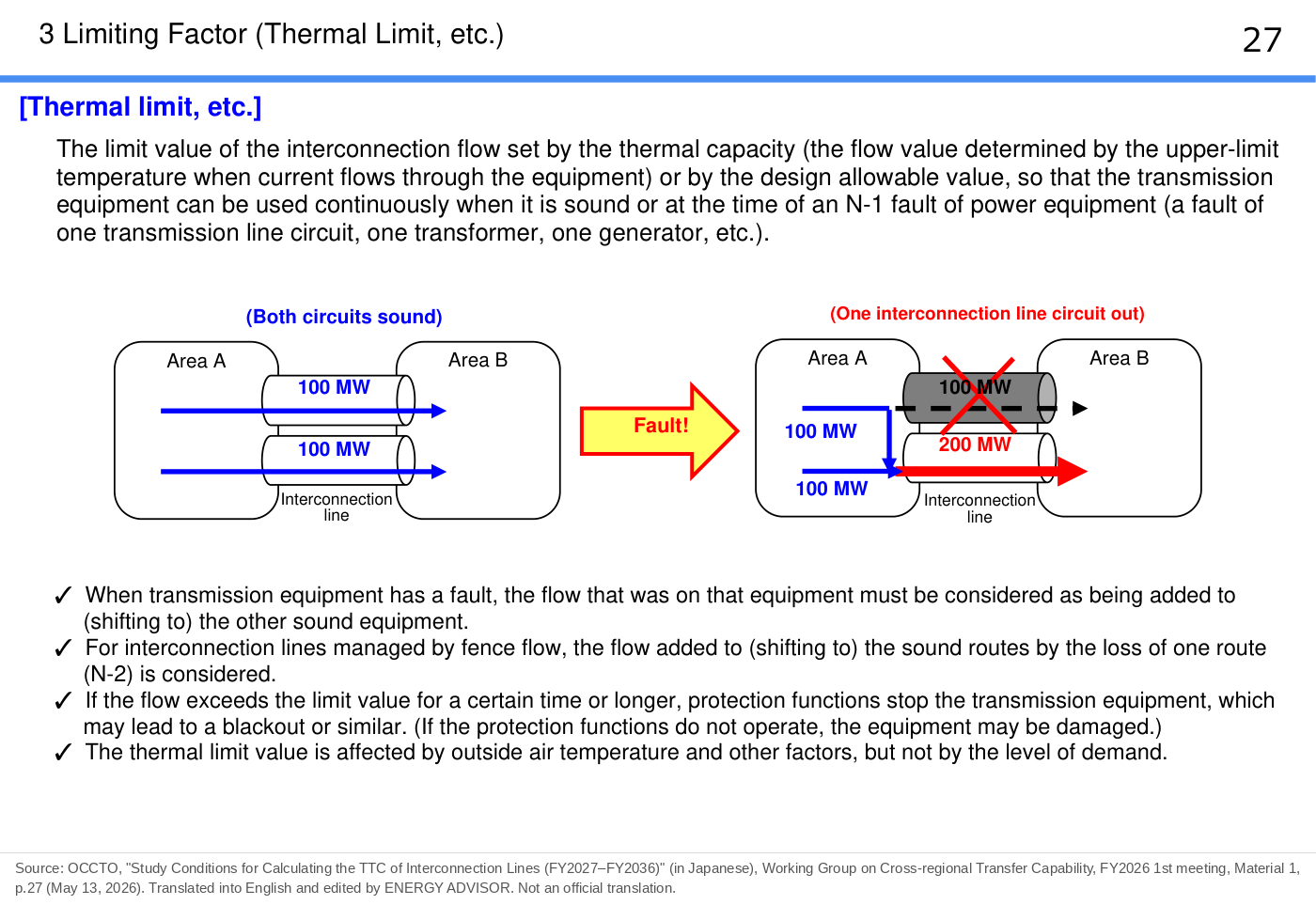
For example, suppose that 100 MW flows on each of two transmission line circuits when both are healthy. If one circuit stops because of a fault, 200 MW flows on the remaining circuit. If the thermal capacity of one circuit is 200 MW, the upper limit that can flow on the two circuits is 200 MW, not 400 MW. If 400 MW were flowing on the two circuits, then when one circuit faulted, 400 MW would shift to the remaining circuit, and even the healthy line would fail, leading to a blackout.
Transmission lines are often operated with two circuits as one set, with one circuit on each side of the tower, for a total of six wires.
The thermal limit is not necessarily set by the interconnection line itself. On the Tohoku–Tokyo Interconnection Line, after the second interconnection line starts operation in November 2027, TTC is expected to be set by the thermal capacity of the transformers at the Minamisoma Substation inside the Tohoku area (see the case-study article in this series, “Tohoku–Tokyo Interconnection Line Falls Short of 10,280 MW Right After Reinforcement (November 2027)”).
(2) Transient Stability
Generators across the whole system rotate in step at the same frequency (in synchronism). When a fault such as a transmission line fault occurs, generators approach an unstable state, and a generator that goes beyond the limit stops automatically. To prevent this, the limit flow at which synchronism can be maintained is calculated in advance by simulation and reflected in TTC.
How transient stability works, with examples, is explained in detail in “Transient Stability” in this series.
(3) Voltage Stability
Voltage stability is the ability to keep the voltage of the power system stable. If equipment fails while the flow on an interconnection line exceeds the voltage stability limit, the voltage may drop and a blackout may occur. For this reason, the upper limit of flow at which voltage can be maintained is calculated and used as TTC.
The more power is sent, the more reactive power (the component of AC power that is involved in maintaining voltage and does no work) is consumed on the transmission line, and the lower the voltage on the receiving side. Beyond a certain amount, voltage can no longer be maintained. When one route stops because of a fault, the flow on the remaining routes increases, reactive power consumption rises sharply, and voltage can drop significantly.
A large voltage drop may lead to a large-scale blackout. For this reason, the maximum interconnection flow at which the voltage after a fault stays at 90% of rated voltage or higher is set in TTC as the voltage stability limit (the example of the Central-Area AC Loop; OCCTO, FY2026 3rd Working Group on Cross-regional Transfer Capability, Material 2, p.12).
Voltage can be adjusted with voltage control equipment such as capacitors. A capacitor is equipment that supplies reactive power to limit voltage drops.
The Kansai–Chugoku Interconnection Line consists of two routes. Because voltage might not be maintained if one route is lost, a voltage stability simulation is carried out, and the flow at which voltage can be maintained is used as TTC.
On the Kansai–Shikoku Interconnection Facility (Anan–Kihoku HVDC Link), when generating stations A and B near the Anan converter station are running only one unit of station B or are fully shut down, TTC toward Kansai (in bipole operation) falls from 1,400 MW to 700 MW because of the voltage stability constraint (limiting overvoltage after a fault on the AC system) (OCCTO, FY2026 2nd Working Group on Cross-regional Transfer Capability, Material 3, slide 128; see the case-study article in this series, “Oil Leak Faults on the Anan–Kihoku HVDC Link and the Revised TTC”).
(4) Frequency Stability Limit
TTC under the frequency stability limit is calculated from the interconnection flow at which the frequency of each area can be maintained when the interconnection line trips and the system separates.
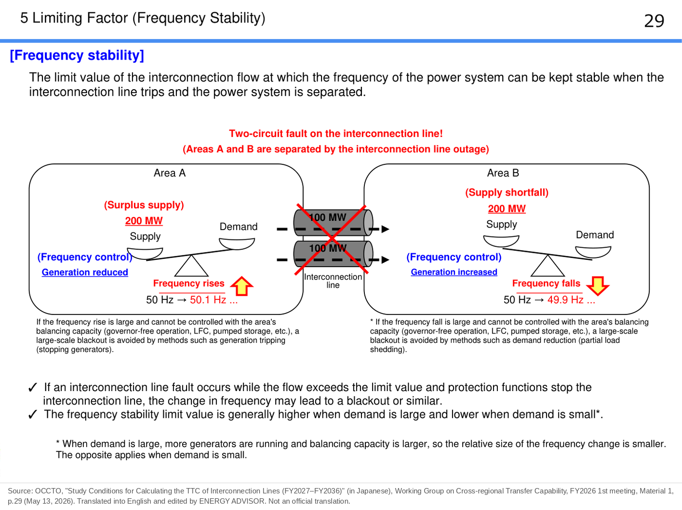
For example, if an interconnection line stops while 200 MW is flowing on it, the sending area has surplus electricity and its frequency rises. The receiving area runs short of electricity and its frequency falls. The larger the interconnection flow, the larger the rise and fall in frequency. To keep frequency within a set range, an upper limit is set on the interconnection flow.
If frequency falls sharply, healthy generators begin to stop automatically, which may lead to a wide-area blackout. To prevent this, there is a mechanism in which an under-frequency relay (UFR) automatically disconnects part of the demand (cuts power to it) when frequency falls sharply, to maintain frequency. A UFR operates when frequency stays below a set value for a set time, and it disconnects a set amount of demand with fairness taken into account (OCCTO, Study Committee on Regulating and Marginal Supply Capability and Long-Term Supply–Demand Balance Evaluation, 66th meeting, Material 8, p.30).
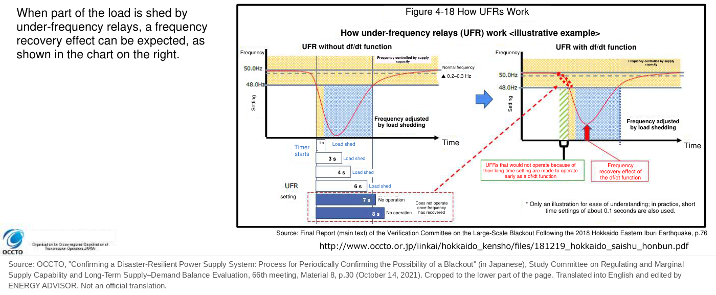
TTC under the frequency stability limit is set so that these UFRs do not operate, that is, so that no blackout occurs, even if the interconnection line trips. Blackouts caused by UFRs are expected in cases such as when many generators stop at once in a large earthquake.
Binding Constraint on Each Interconnection Line in FY2026
TTC and the binding constraints for weekday daytime in August FY2026 are as follows.
| Interconnection line | Direction | TTC (MW) | Binding constraint |
|---|---|---|---|
| Hokkaido–Honshu Interconnection Facility | Toward Hokkaido / toward Tohoku | 900 [600] / 700 [500] | (1) [(1)] / (3) [(1)] |
| Tohoku–Tokyo Interconnection Line | Toward Tohoku / toward Tokyo | 2,360 / 5,250 | (1) / (1) |
| Tokyo–Chubu Interconnection Facility | Toward Tokyo / toward Chubu | [1,800] / [1,800] | (1) / (1) |
| Chubu fence | Toward Hokuriku and Kansai / toward Chubu | [2,730] / [3,010] | (2) / (3) |
| Hokuriku fence | Toward Hokuriku / toward Chubu and Kansai | [2,820] / [3,570] | (3) / (2) |
| Kansai fence | Toward Kansai / toward Chubu and Hokuriku | [2,730] / [3,010] | (2) / (3) |
| Kansai–Chugoku Interconnection Line | Toward Kansai / toward Chugoku | 4,650 / 4,700 | (3) / (3) |
| Kansai–Shikoku Interconnection Facility | Toward Kansai / toward Shikoku | 900 / 0 | (1) / (2) |
| Chugoku–Shikoku Interconnection Line | Toward Chugoku / toward Shikoku | 1,450 / 1,200 | (1) / (1) |
| Chugoku–Kyushu Interconnection Line | Toward Chugoku / toward Kyushu | 2,340 / 540 | (4) / (4) |
(Values without square brackets are TTC when no maintenance work is under way; values in [ ] are the minimum TTC during maintenance work. (1) thermal limit, (2) transient stability, (3) voltage stability, (4) frequency stability limit. Source: OCCTO, FY2026 2nd Working Group on Cross-regional Transfer Capability, Material 1, pp.3–4)
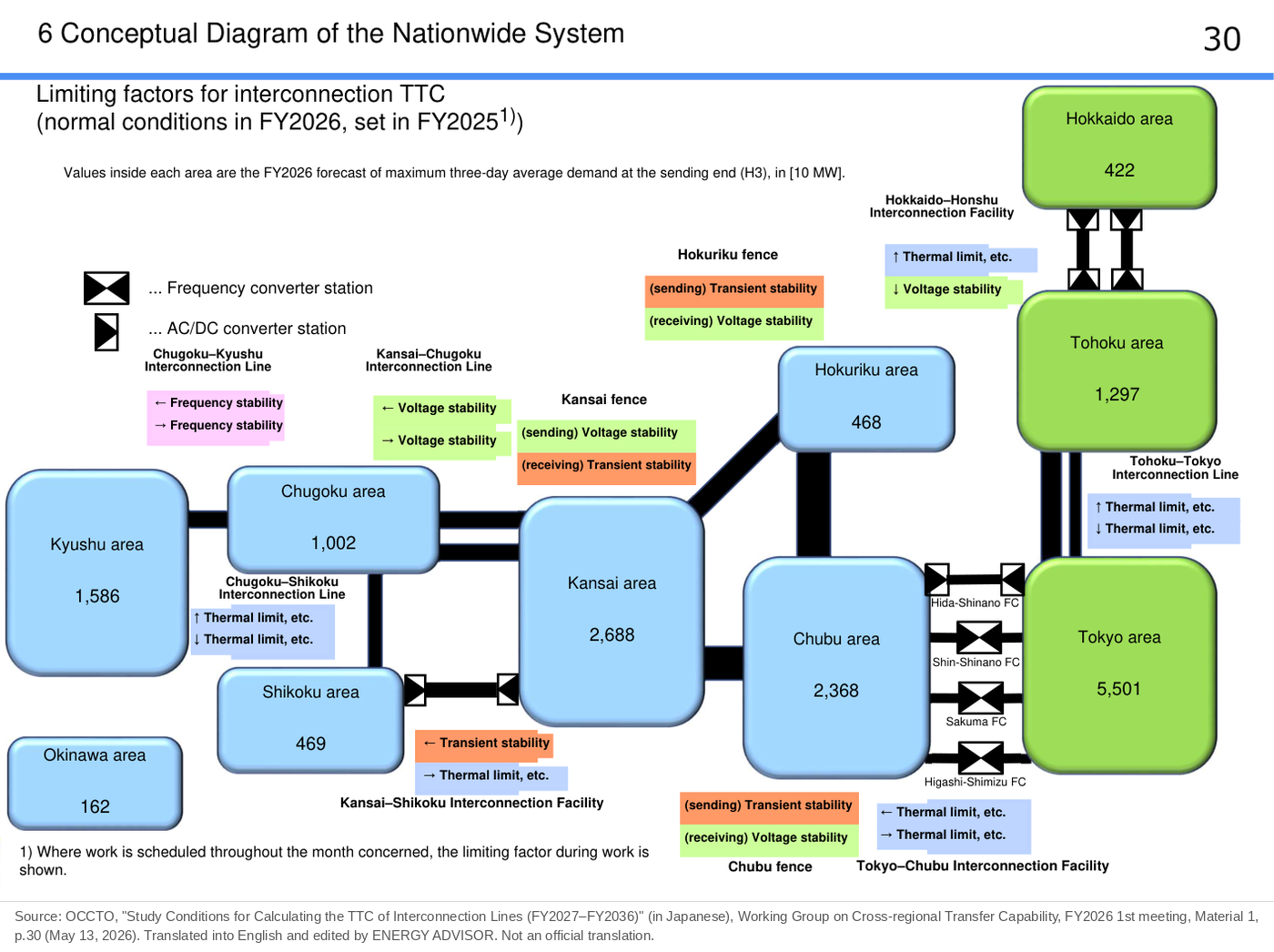
Compared with the FY2022 map, the binding constraints changed as follows.
| Limiting factor | FY2022 (map for weekday daytime in August) | FY2026 (weekday daytime in August) |
|---|---|---|
| (1) Thermal limit | 7 of the 10 interconnection lines | Both directions of Tohoku–Tokyo, Tokyo–Chubu and Chugoku–Shikoku; Kansai–Shikoku toward Kansai; Hokkaido–Honshu toward Hokkaido (the values during maintenance work are (1) in both directions) |
| (2) Transient stability | 2 (Tohoku–Tokyo and others) | The main binding constraint of the Chubu, Hokuriku and Kansai fences; Kansai–Shikoku toward Shikoku |
| (3) Voltage stability | Only Kansai–Chugoku toward Kansai | Both directions of Kansai–Chugoku; Chubu fence toward Chubu, Hokuriku fence toward Hokuriku, and Kansai fence toward Chubu and Hokuriku; Hokkaido–Honshu toward Tohoku (value when no maintenance work is under way) |
| (4) Frequency stability limit | 3 (Chugoku–Kyushu and others) | Only both directions of Chugoku–Kyushu |
There are two main changes. The first is that the links among Chubu, Hokuriku and Kansai became an AC loop (the Central-Area AC Loop). In an AC loop, the system does not separate even if one route is lost, so the frequency stability study itself is no longer carried out, and the main binding constraint became transient stability. The second is Tohoku–Tokyo toward Tokyo. In FY2026, the thermal limit ((1)) is the binding constraint in many months, and all long-term values from FY2028 onward are the thermal limit ((1)).
Binding constraints change with direction, month and time of day. For this reason, counting “how many interconnection lines are set by a given factor” does not fit FY2026 operation.
Chugoku–Kyushu Interconnection Line Set by the Frequency Stability Limit
In the Kyushu area, output curtailment (asking generators to stop temporarily) of solar and other renewables is often carried out in spring and autumn, when demand is low. Surplus electricity in Kyushu flows to the Honshu side through the Chugoku–Kyushu Interconnection Line. When the flow reaches the upper limit set by the frequency stability constraint and supply and demand are expected to fall out of balance, renewable output is unavoidably curtailed to hold down generation in the Kyushu area.
If a fault on the interconnection line breaks the link while the flow is above the limit, a large-scale blackout may occur over a wide area. Studying this in advance prevents large-scale blackouts. For weekday daytime in August FY2026, the TTC of the Chugoku–Kyushu Interconnection Line is 2,340 MW toward Chugoku and 540 MW toward Kyushu, set in both directions by the frequency stability limit.
Fences and Fringe
A fence is a cross-section that sums the power flows of multiple interconnection facilities connected to an area. In a section with multiple AC routes, when one route stops, electricity shifts to the remaining routes. For this reason, TTC is managed not for each line but by the total flow (the fence). The Kansai–Chugoku Interconnection Line with its two routes and, from FY2026, the Central-Area AC Loop (the Chubu, Hokuriku and Kansai fences) use this method.
Fringe is the amount deducted from TTC in advance to allow for deviations between actual and scheduled flows. The fringe of the Central-Area AC Loop was corrected from 380 MW to 390 MW at the Working Group on Cross-regional Transfer Capability in September 2026, and it is used to calculate TTC for FY2027–FY2036.
Why Maintenance Outages Lower TTC
Transmission line and substation equipment is sometimes taken out of service on a planned basis for inspection or construction (maintenance outages). Because the value is recalculated so that operation stays stable even if another piece of equipment fails while that equipment is out of service, TTC becomes smaller than under normal conditions. OCCTO’s materials explain that taking equipment out of service in an AC loop increases the impedance (how hard it is for AC electricity to flow) within the loop and lowers limits such as the transient stability limit. Because the size of the drop differs greatly depending on which equipment is taken out, TTC is calculated separately for each piece of equipment with a large impact.
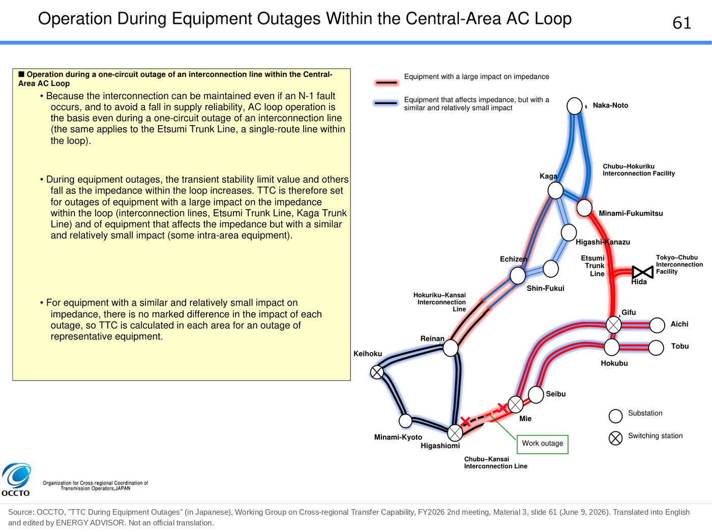
In OCCTO’s published annual values, the minimum TTC during maintenance work is shown in [ ]. For the Central-Area AC Loop in FY2026, only the [ ] values are shown for all fences for weekday daytime from April to November. A case in which the actual TTC toward Chubu was operated at the value during maintenance work and market splitting increased is examined in the case-study article in this series, “Increase in Chubu Market Splitting After the Central-Area AC Loop Started.”
Calculation and Publication Process (New Schedule from FY2026)
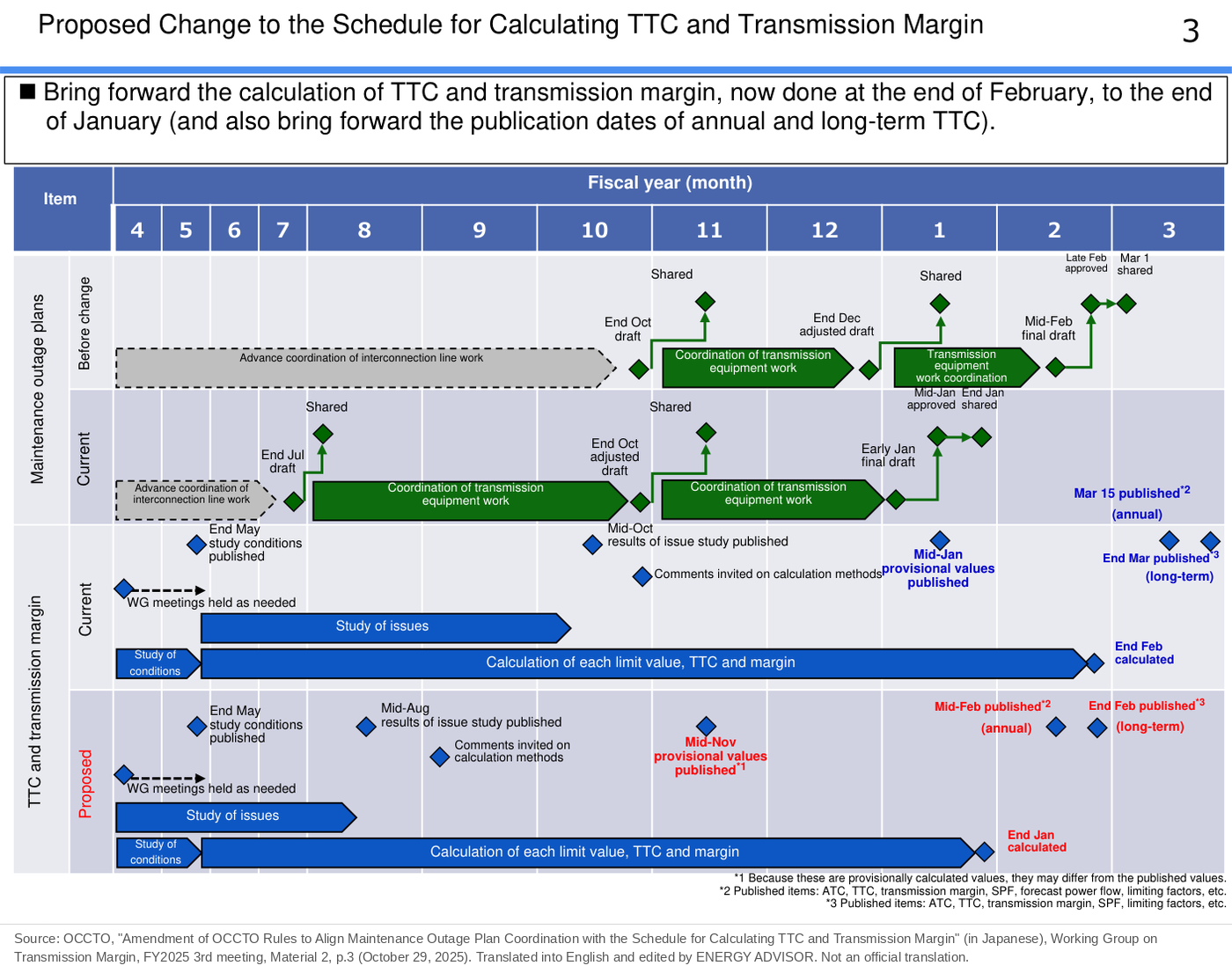
TTC is calculated by OCCTO, reviewed at the Working Group on Cross-regional Transfer Capability and then published. Starting with the FY2026 work, the schedule was brought forward to align it with the coordination schedule for maintenance outage plans.
| Item | Before the amendment | After the amendment (from the FY2026 work) |
|---|---|---|
| Calculation of TTC and transmission margin | End of February | End of January |
| Publication of annual TTC | March 15 each year | Mid-February each year |
| Publication of long-term TTC | Last day of March each year | Last day of February each year |
(Source: OCCTO, FY2025 3rd Working Group on Transmission Margin, Material 2, pp.3 and 5; Board of Councilors, Agenda Item 1, “Partial Amendment of the Operational Rules”)
Under the amended process, the study conditions are published at the end of May and the results of the study of issues in mid-August, followed by a public consultation on the calculation method. Provisional values are published in mid-November, and the calculation is done by the end of January. The values for FY2027–FY2036 are scheduled to be published in February 2027.
After the annual publication, values are also updated monthly, weekly and for the next day to reflect the conditions at each point.
The materials of the Working Group on Cross-regional Transfer Capability are open to anyone, so the calculation conditions and results can be checked.
Checking Values on the System Information Service
Daily TTC values are published on OCCTO’s system information service (https://occtonet3.occto.or.jp/public/dfw/RP11/OCCTO/SD/LOGIN_login#). The TTC and flow status of each interconnection line can be checked as figures and graphs. Since March 2026, the values for the central area have been shown by fence.
Summary
The TTC of an interconnection line is the upper limit of the power flow that can flow stably on the line. The smallest of the four limit values, the “thermal limit,” “transient stability,” “voltage stability” and “frequency stability limit,” becomes TTC.
In FY2026, with the start of the Central-Area AC Loop, the main binding constraint among Chubu, Hokuriku and Kansai changed from the frequency stability limit to transient stability. The Chugoku–Kyushu Interconnection Line is now the only one set by the frequency stability limit. TTC is calculated by the end of January each year, and annual values are published in mid-February and long-term values at the end of February. Daily values can be checked on the system information service.
This article is based on published materials from the Ministry of Economy, Trade and Industry and its Agency for Natural Resources and Energy, the Electricity and Gas Market Surveillance Commission, the Organization for Cross-regional Coordination of Transmission Operators (OCCTO) and other sources. The English translations of figures are by ENERGY ADVISOR and are not official translations. When using this information for decisions, please check the original sources. When we find an error, we correct the article and note the date of the correction.
Sources
- OCCTO, FY2026 2nd Working Group on Cross-regional Transfer Capability, Material 1, “Total Transfer Capability of Interconnection Lines for FY2026–FY2035 (Annual and Long-Term)” (in Japanese), pp.3–4 (annual TTC for FY2026, weekday daytime), p.20 (long-term TTC), June 9, 2026. https://www.occto.or.jp/assets/iinkai/unyouyouryou/26002/2026_2_1.pdf
- OCCTO, FY2026 2nd Working Group on Cross-regional Transfer Capability, Material 2, “Calculation Methods and Results of TTC for Each Interconnection Line” (in Japanese), slide 58 (fence management), slide 64 (rated thermal capacity and ambient temperature of the Mie–Higashiomi Line and Echizen–Reinan Line), June 9, 2026. https://www.occto.or.jp/assets/iinkai/unyouyouryou/26002/2026_2_2.pdf
- OCCTO, FY2026 2nd Working Group on Cross-regional Transfer Capability, Material 3, “TTC During Equipment Outages” (in Japanese), slide 61 (equipment outages and impedance), June 9, 2026. https://www.occto.or.jp/assets/iinkai/unyouyouryou/26002/2026_2_3.pdf
- OCCTO, FY2026 4th Working Group on Cross-regional Transfer Capability, Material 1, “Revision of the Study Conditions for Calculating TTC of Interconnection Lines (FY2027–FY2036)” (in Japanese), p.2 (correction of the fringe), September 7, 2026. https://www.occto.or.jp/assets/iinkai/unyouyouryou/26004/2026_4_1.pdf
- OCCTO, FY2025 3rd Working Group on Transmission Margin, Material 2, “Amendment of OCCTO Rules to Align Maintenance Outage Plan Coordination with the Schedule for Calculating TTC and Transmission Margin” (in Japanese), pp.3 and 5, October 29, 2025. https://www.occto.or.jp/assets/iinkai/margin_kentoukai/25003/2025_3_2_margin_kaisei.pdf
- OCCTO, Board of Councilors, Agenda Item 1, “Partial Amendment of the Operational Rules” (in Japanese) (amendment of the provisions on the schedule for calculating TTC and transmission margin, Articles 126 and 129). https://www.occto.or.jp/assets/hyougiinkai/02042677/2025_3_1.pdf
- OCCTO, Working Group on Cross-regional Transfer Capability (in Japanese). https://www.occto.or.jp/iinkai/unyouyouryou/index.html
- OCCTO, system information service (in Japanese). https://occtonet3.occto.or.jp/public/dfw/RP11/OCCTO/SD/LOGIN_login#
- OCCTO, FY2026 2nd Working Group on Cross-regional Transfer Capability, Material 3, “TTC During Equipment Outages” (in Japanese), slide 128 (constraints on the Kansai–Shikoku Interconnection Facility when generators are out of service), June 9, 2026. https://www.occto.or.jp/assets/iinkai/unyouyouryou/26002/2026_2_3.pdf
- OCCTO, FY2026 3rd Working Group on Cross-regional Transfer Capability, Material 2, “Expansion of Emergency TTC of the Central-Area AC Loop” (in Japanese), p.12 (criteria for voltage stability) (Chubu Electric Power Grid, Hokuriku Electric Power Transmission & Distribution and Kansai Transmission and Distribution), July 13, 2026. https://www.occto.or.jp/assets/iinkai/unyouyouryou/26003/2026_3_2.pdf
- OCCTO, Study Committee on Regulating and Marginal Supply Capability and Long-Term Supply–Demand Balance Evaluation, 66th meeting, Material 8, “Confirming a Disaster-Resilient Power Supply System” (in Japanese), p.30 (how under-frequency relays work). https://www.occto.or.jp/assets/iinkai/chouseiryoku/2021/files/chousei_66_08.pdf
- OCCTO, FY2026 1st Working Group on Cross-regional Transfer Capability, Material 1, “Study Conditions for Calculating TTC of Interconnection Lines (FY2027–FY2036)” (in Japanese), reference material “Overview of TTC,” p.25 (definition of TTC), p.26 (approach to upper limits), p.27 (thermal limit), p.29 (frequency stability limit), p.30 (conceptual diagram of the nationwide system), May 13, 2026. https://www.occto.or.jp/assets/iinkai/unyouyouryou/26001/2026_1_1.pdf
- OCCTO, 8th meeting of the Working Group on Future Transmission Capacity and Related Matters, Material 6, “Summary of Studies in This Working Group and Next Steps” (in Japanese), June 13, 2025 (working group secretariat). https://www.occto.or.jp/iinkai/chouseiryoku/jukyuchousei/2025/files/unyouyouryousagyoukai_8_06.pdf