The total transfer capability (TTC) of an interconnection line (the upper limit of electricity that can flow on it) is set by the smallest of the limit values of four limiting factors: the thermal limit, transient stability, voltage stability and the frequency stability limit. The overall approach is explained in “Total Transfer Capability (TTC) of Interconnection Lines” in this series. This article explains one of them, transient stability.
Definition of Transient Stability
In a power system, many generators run at the same frequency. This is called synchronism. The degree to which generators can keep running stably in synchronism with each other is called transient stability (synchronous stability) (Organization for Cross-regional Coordination of Transmission Operators, JAPAN [OCCTO], Study Committee on Regulating and Marginal Supply Capability and Long-Term Supply–Demand Balance Evaluation, 66th meeting, Material 8, p.29).
When a change in conditions such as a transmission line fault occurs, generators can fall into an unstable state in which they cannot keep running. A generator that becomes unstable stops automatically. OCCTO’s Network Codes (Article 64) set, as a standard the power system must meet, that the stability of synchronous operation of generators is maintained even after a fault on a single piece of equipment, such as one transmission line circuit (an N-1 contingency), occurs and the equipment is disconnected.
Mechanism of Transient Stability
An AC generator produces a voltage wave in step with its rotation. The offset between the positions of the waves of different generators is called the phase angle. The larger the phase angle difference between the sending generator and the receiving system, the more power flows through the transmission line.
However, there is an upper limit to the power that can be sent. The larger the reactance of the transmission line (how hard it is for AC electricity to flow; the main component of impedance), the larger the phase angle difference needed to send the same power. When the phase angle difference goes beyond a certain range, the generator can no longer keep rotating in step with the system. This state is called loss of synchronism (pole slipping).
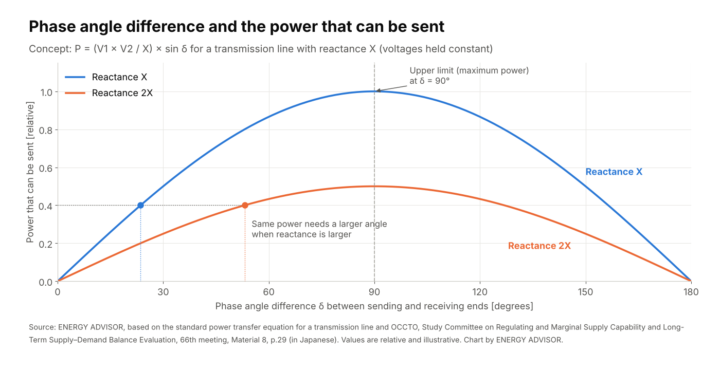
When a transmission line fault occurs, a generator that suddenly cannot send power at that moment accelerates, and the phase angle difference widens. When the faulted circuit is disconnected, the reactance of the remaining transmission lines is larger than before the fault. If the swing in phase angle (power swing) then settles, the generator can keep running. If the swing does not settle, the generator loses synchronism and stops.
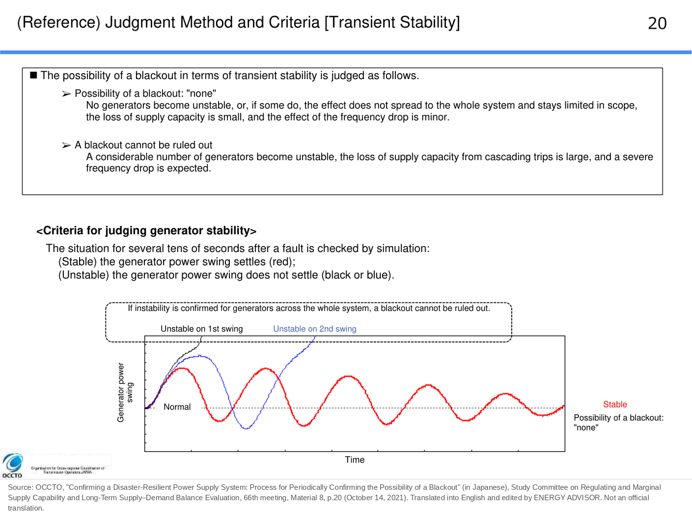
OCCTO’s materials state that the situation for several tens of seconds after a fault occurs is checked by simulation, and the result is judged “stable” if the generator’s power swing converges and “unstable” if it does not (66th meeting, Material 8, p.20). The larger the flow before the fault, the larger the swing after the fault. For this reason, the upper limit of flow at which generators can stay in synchronism even if the assumed fault occurs is calculated in advance by simulation and reflected in TTC.
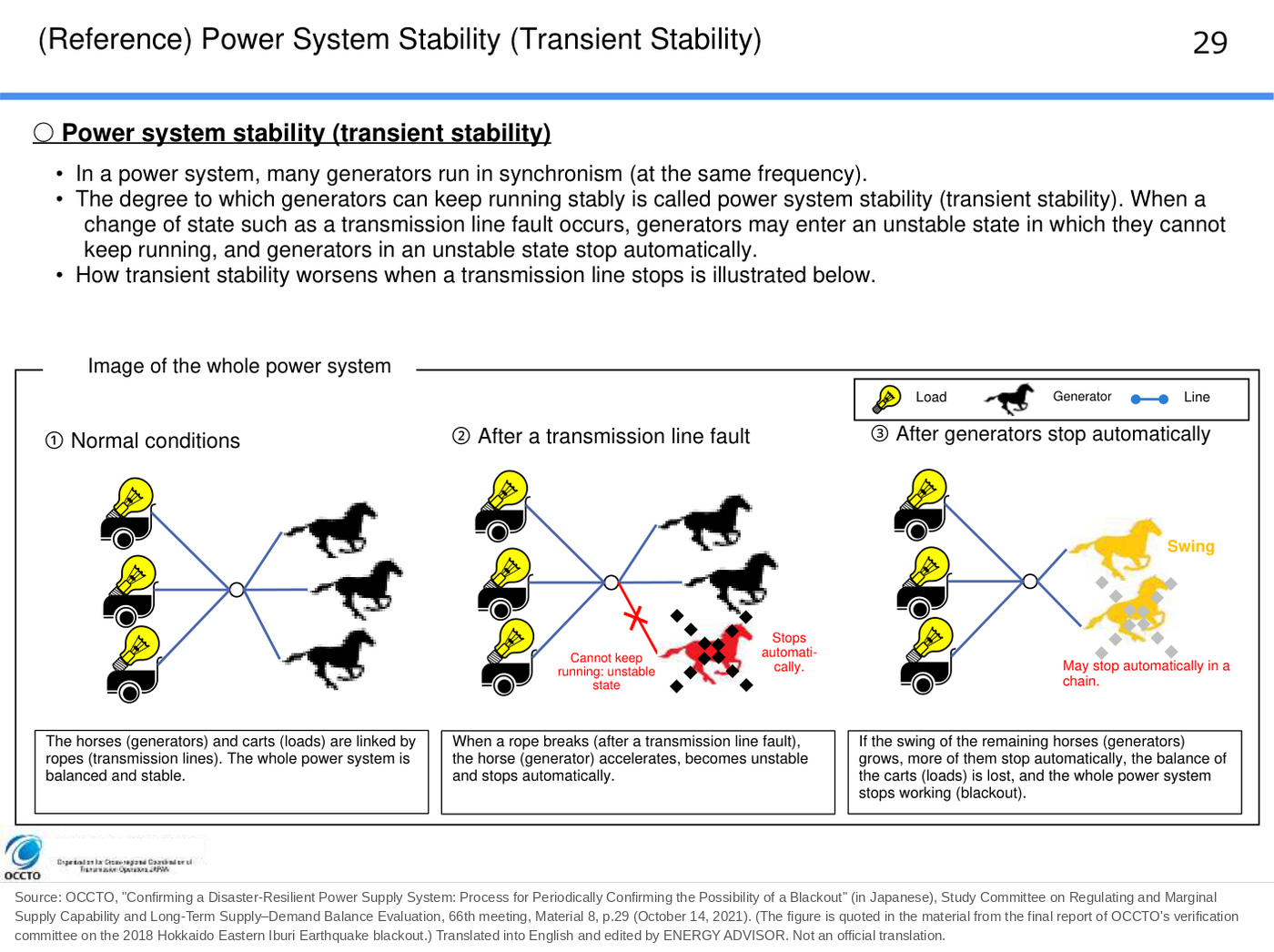
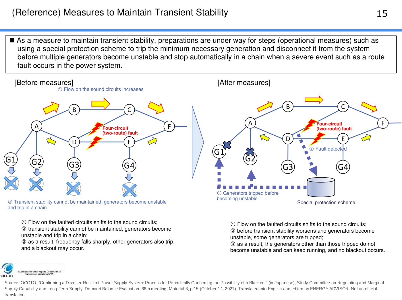
If unstable generators stop one after another, frequency falls sharply, which may lead to a wide-area blackout. OCCTO’s FY2021 materials state that, as a countermeasure, preparations were under way for special protection schemes (SPS) that disconnect some generators from the system before they become unstable in a severe fault such as a route outage (66th meeting, Material 8, p.15).
Why Equipment Outages Lower the Limit
OCCTO’s materials explain the Central-Area AC Loop (the system in which Chubu, Hokuriku and Kansai are linked in an AC loop) as follows (FY2026 2nd Working Group on Cross-regional Transfer Capability, Material 3, slides 61 and 62).
- The larger the impedance between generators in the Chubu area and the system west of the Chubu area, the lower the transient stability limit tends to be
- Taking equipment out of service increases the impedance within the loop and lowers limits such as the transient stability limit
When a transmission line is taken out of service for work, electricity has to be sent on the remaining lines only, and impedance increases. If a fault occurs in that state, it becomes harder for generators to stay in synchronism. For this reason, TTC is smaller than under normal conditions while equipment is out of service for work.
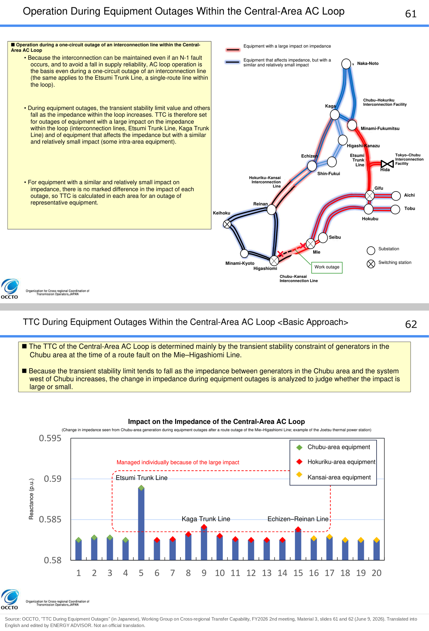
Example 1: The Central-Area AC Loop (from 2026)
In April 2026, the interconnection lines among the three areas of Chubu, Hokuriku and Kansai started operating as an AC loop (the Central-Area AC Loop). TTC is managed by the sum of the flows on the two interconnection facilities connected to each area (a fence).
Before the loop started, TTC between the Chubu, Hokuriku and Kansai areas was set by the frequency stability limit (the limit up to which frequency can be maintained when an interconnection line trips and the areas separate). In an AC loop, the system does not separate even if one route is lost. For this reason, the frequency stability study is no longer carried out, and the main binding constraint became transient stability.
OCCTO’s materials (FY2026 2nd Working Group on Cross-regional Transfer Capability, Material 3, slide 62) state that the TTC of the Central-Area AC Loop is set mainly by the transient stability of generators in the Chubu area at the time of a route outage (a fault in which both circuits stop) on the Mie–Higashiomi Line (the Chubu–Kansai Interconnection Line).
TTC for weekday daytime in August FY2026 (minimum during maintenance work) is as follows.
| Fence | Direction | TTC (MW) | Binding constraint |
|---|---|---|---|
| Chubu fence | Toward Hokuriku and Kansai | [2,730] | Transient stability |
| Hokuriku fence | Toward Chubu and Kansai | [3,570] | Transient stability |
| Kansai fence | Toward Kansai | [2,730] | Transient stability |
([ ] indicates the minimum TTC during maintenance work. Source: OCCTO, FY2026 2nd Working Group on Cross-regional Transfer Capability, Material 1, p.3)
From April to September 2026, maintenance outages of transmission lines within the loop continued, and TTC toward Chubu was, for much of the period, the same as the value during maintenance work in the published annual values. The results and the effect on the market are examined in the case-study article in this series, “Increase in Chubu Market Splitting After the Central-Area AC Loop Started.”
Example 2: Tohoku–Tokyo (Moving to a Thermal Constraint with Reinforcement)
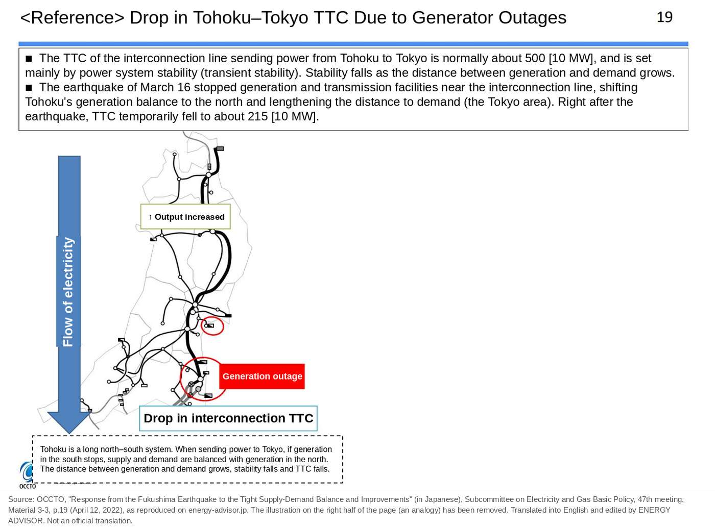
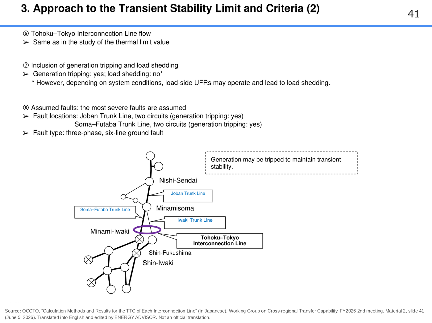
The Tohoku–Tokyo Interconnection Line is an important interconnection line for sending large amounts of power from generators in the Tohoku area to the Tokyo area. In 2022, transient stability was its binding constraint. As a result, its TTC had the characteristic of changing when generators or transmission lines near the interconnection line stopped.
In the earthquake off the coast of Fukushima Prefecture on March 16, 2022, generators near the interconnection line stopped because of the earthquake, and TTC fell sharply. OCCTO’s materials state that TTC from Tohoku to Tokyo is normally around 5,000 MW and is set mainly by system stability (transient stability). Because power sources and transmission facilities near the interconnection line stopped in the earthquake, Tohoku’s generation became concentrated in the north and the distance to demand (the Tokyo area) became longer, so TTC right after the earthquake temporarily fell to about 2,150 MW (OCCTO, “Response from the Fukushima Earthquake to the Tight Supply-Demand Balance and Improvements,” p.19).
| Point in time | TTC from Tohoku to Tokyo |
|---|---|
| Normal | Around 5,000 MW |
| Right after the earthquake of March 16, 2022 | Temporarily about 2,150 MW |
In FY2026, TTC toward Tokyo has the thermal limit ((1)) as the binding constraint in many months, and transient stability ((2)) in part of the winter (February and others).
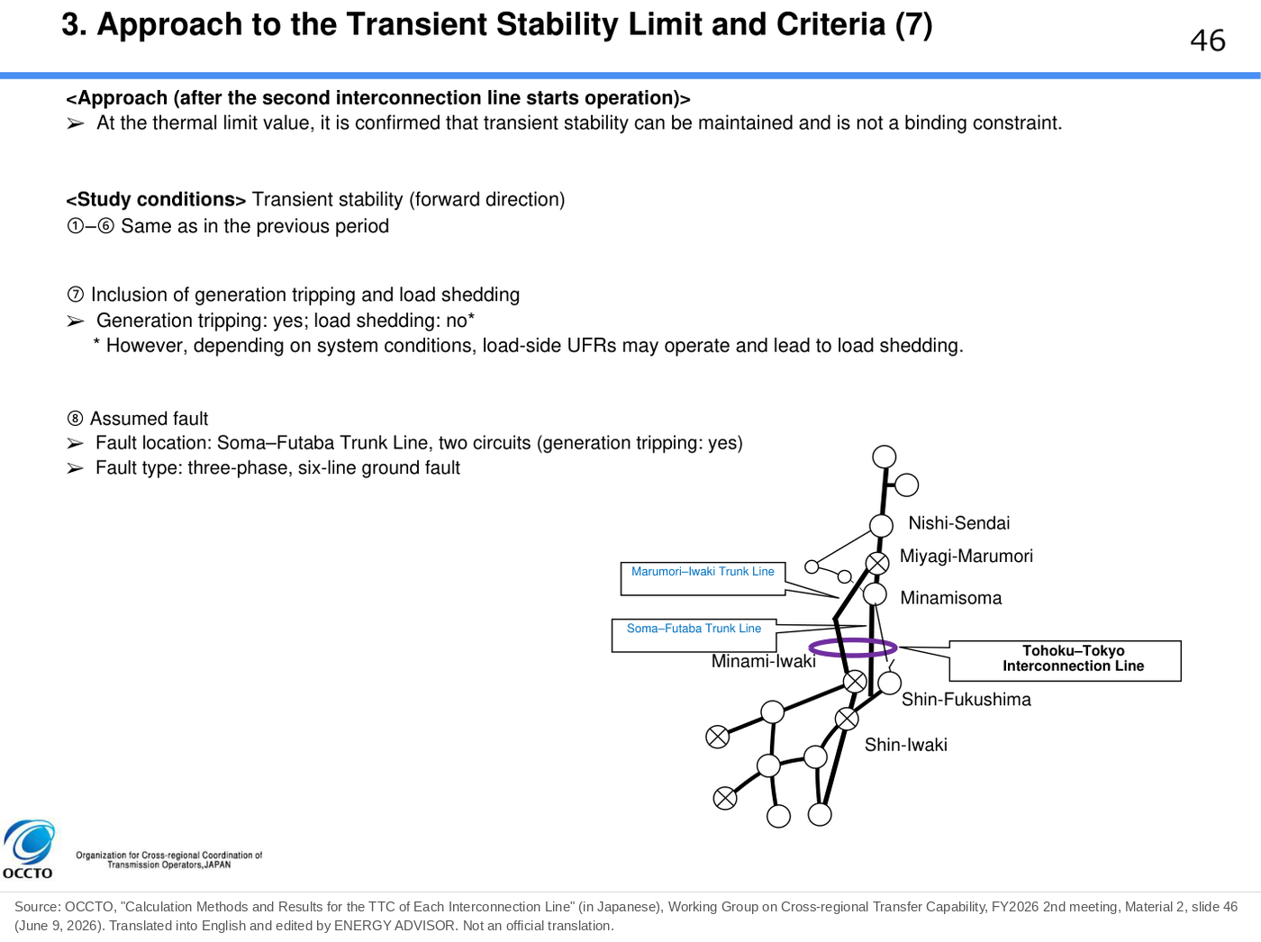
In November 2027, the 500 kV second interconnection line (Marumori–Iwaki Trunk Line, etc.) is scheduled to start operation. OCCTO’s materials state that with more 500 kV routes, transient stability at the time of a simultaneous fault on both circuits of each 500 kV transmission line (an N-2 contingency) improves greatly and far exceeds the thermal limit value. For this reason, after the start of operation, the transient stability limit will not be calculated; instead, the method changes to confirming that transient stability is maintained at the flow of the thermal limit value.
| Item | Before the second interconnection line starts | After it starts |
|---|---|---|
| Transmission lines forming the interconnection | 500 kV Soma–Futaba Trunk Line + 275 kV Iwaki Trunk Line (4 circuits in total) | 500 kV Soma–Futaba Trunk Line + Marumori–Iwaki Trunk Line (4 circuits in total) |
| Transient stability | A limit value is calculated for each assumed fault | No limit value is calculated; it is confirmed that stability is secured at the thermal limit value |
| Binding constraint of long-term TTC (toward Tokyo) | – | Thermal limit in all of FY2028–FY2035 |
(Source: OCCTO, FY2025 3rd Working Group on Cross-regional Transfer Capability, Material 3, slides 2, 3 and 7; FY2026 2nd Working Group on Cross-regional Transfer Capability, Material 1, p.20)
When 500 kV routes are added, the transient stability constraint falls away, and a different constraint (here, the thermal capacity of substation transformers) sets the upper limit. How this works for Tohoku–Tokyo is explained in detail in the case-study article in this series, “Tohoku–Tokyo Interconnection Line Falls Short of 10,280 MW Right After Reinforcement (November 2027).”
Summary
The degree to which generators can keep running stably in synchronism with each other is called transient stability. The larger the power sent, and the larger the reactance (impedance), the larger the phase angle difference, and the more easily generators lose synchronism after a fault. For this reason, the upper limit of flow at which synchronism can be maintained even after the assumed fault is calculated in advance by simulation and reflected in TTC.
In FY2026, transient stability became the main binding constraint for each fence of the Central-Area AC Loop, and it is also the reason TTC falls during maintenance outages of equipment. On Tohoku–Tokyo, by contrast, the reinforcement adds 500 kV routes, so the transient stability constraint falls away and the line moves to a thermal constraint.
This article is based on published materials from the Ministry of Economy, Trade and Industry and its Agency for Natural Resources and Energy, the Electricity and Gas Market Surveillance Commission, the Organization for Cross-regional Coordination of Transmission Operators (OCCTO) and other sources. The English translations of figures are by ENERGY ADVISOR and are not official translations. When using this information for decisions, please check the original sources. When we find an error, we correct the article and note the date of the correction.
Sources
- OCCTO, Study Committee on Regulating and Marginal Supply Capability and Long-Term Supply–Demand Balance Evaluation, 66th meeting, Material 8, “Confirming a Disaster-Resilient Power Supply System” (in Japanese), p.15 (special protection schemes), p.20 (stability criteria), p.29 (definition and diagram of system stability), p.31 (excerpt of Article 64 of the Network Codes). https://www.occto.or.jp/assets/iinkai/chouseiryoku/2021/files/chousei_66_08.pdf
- OCCTO, FY2026 2nd Working Group on Cross-regional Transfer Capability, Material 1, “Total Transfer Capability of Interconnection Lines for FY2026–FY2035 (Annual and Long-Term)” (in Japanese), pp.3–4 and p.20, June 9, 2026. https://www.occto.or.jp/assets/iinkai/unyouyouryou/26002/2026_2_1.pdf
- OCCTO, FY2026 2nd Working Group on Cross-regional Transfer Capability, Material 3, “TTC During Equipment Outages” (in Japanese), slides 61 and 62, June 9, 2026. https://www.occto.or.jp/assets/iinkai/unyouyouryou/26002/2026_2_3.pdf
- OCCTO, FY2025 3rd Working Group on Cross-regional Transfer Capability, Material 3, “Method for Calculating TTC After Reinforcement of the Tohoku–Tokyo Interconnection Line” (in Japanese), slides 2, 3 and 7, December 15, 2025. https://www.occto.or.jp/assets/iinkai/unyouyouryou/25003/2025_3_3.pdf
- OCCTO, “Response from the Fukushima Earthquake to the Tight Supply-Demand Balance and Improvements” (in Japanese), p.19, “ Drop in Tohoku–Tokyo TTC Due to Generator Outages” (Advisory Committee for Natural Resources and Energy, Electricity and Gas Industry Committee, Subcommittee on Electricity and Gas Basic Policy, 47th meeting, Material 3-3, April 12, 2022). https://www.meti.go.jp/shingikai/enecho/denryoku_gas/denryoku_gas/pdf/047_03_03.pdf
- OCCTO, FY2026 2nd Working Group on Cross-regional Transfer Capability, Material 2, “Calculation Methods and Results of TTC for Each Interconnection Line” (in Japanese), slide 41 (assumed faults for transient stability on Tohoku–Tokyo), slide 45 (criteria), slide 46 (treatment after the second interconnection line starts), slide 69 (criteria for the Central-Area AC Loop), June 9, 2026. https://www.occto.or.jp/assets/iinkai/unyouyouryou/26002/2026_2_2.pdf